Installation instructions Description
This article is to help the after-sales team and engineers at a site to complete the installation and training work. Please ensure that site preparation is complete before performing the following operations.
The sample machine is E3015T6/F3015T6 sheet-tube integrated cutting machine whose energy source is a fiber laser.
Configuration: double platforms for thin sheet metal, pipe cutting lathe bed is 6 m, Chuck diameter 220 mm, cast iron lathe bed, cast aluminum beam, independent electronic control cabinet.
Specific parameter configuration can refer to the E3015T/F3015T Dual-use fiber laser cutting machine or email me on the machine configuration.
Installation Process
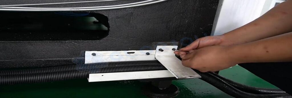
1. Machine bed installation
Place the sheet metal support plate on the bed and fix it to load the front sheet metal cover.
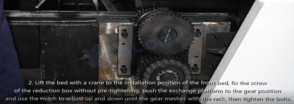
Lift the bed with a crane to the installation position of the front bed, fix the screw of the reduction box without pre-tightening, push the exchange platform to the gear position, and use the notch to adjust up and down until the gear meshes with the rack, then tighten the bolts.
2. Crossbeam installation
1) Hoist the beam to the sliders on both sides of the bed.
2) Put the beam on the slide of the machine bed and fix it with hexagonal screws, and insert the oil circuit well.
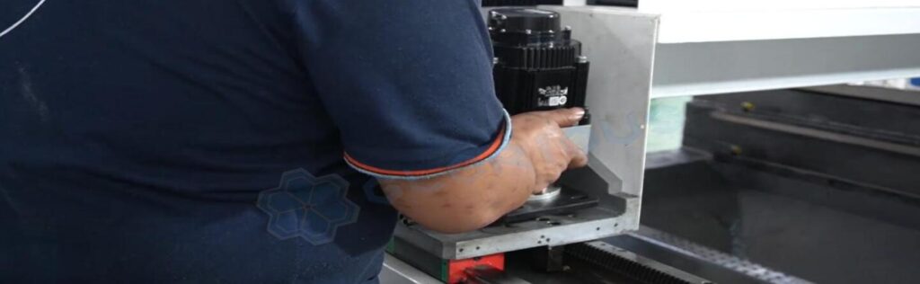
3) Put the motor on both sides of the beam and fix it without pre-tightening. Use the solder wire to adjust the meshing degree between the gear and the rack to 0.03-0.05mm through the adjusting block, then tighten the tightening nut.
4) Install the beam guard at the position of the pipe machine, then install the ventilation system.
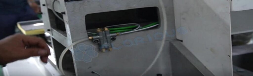
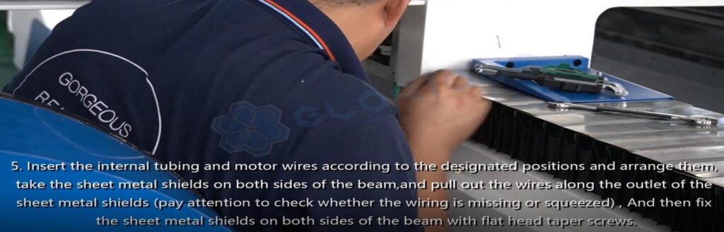
5) Insert the internal tubing and motor wires according to the designated positions and arrange them, take the sheet metal shields on both sides of the beam, and pull out the cables along the outlet of the sheet metal shields(Pay attention to check whether the wiring is missing or squeezed). And then, fix the sheet metal shields on both sides of the beam with flat-head taper screws.
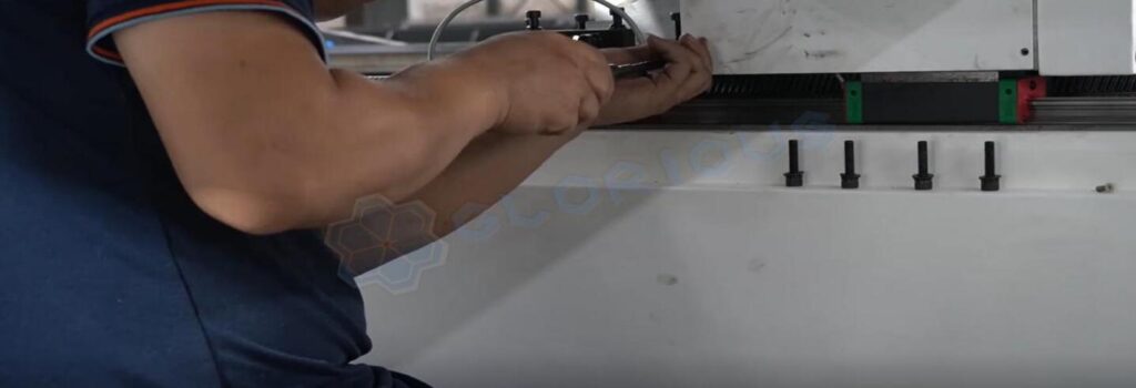
6) Take the drag chain, lead the regular lines in the beam to the inside of the drag chain, install the drag chain according to the mounting holes, and finally, cover the drag chain guard.

7) Fix the organ cover to the front and rear ends of the beam, and fix the anti-burning plates of the organ cover on both sides after Installation.
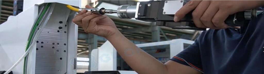
3. Laser head installation
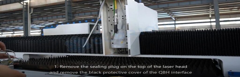
1) Remove the sealing plug on the top of the laser head and remove the black protective cover of the QBH interface.
2) Pick up the laser head horizontally, align the red dot on the laser head with the red dot on the QBH, and then insert the QBH into the laser head interface.
3) Align the red point at the end of the QBH interface with the red point of the handwheel; then remove the QBH dustproof cover, and the red mark of the fiber output end is aligned QBH red mark and insert straight to the bottom; then turn the QBH handwheel clockwise.
It is in place when you hear the “Da” sound, then pull the handwheel up and turn clockwise again.
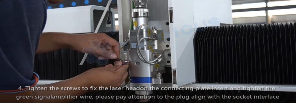
4) Tighten the screws to fix the laser head on the connecting plate. Insert and tighten the green signal amplifier wire, and pay attention to the plug aligned with the socket interface.
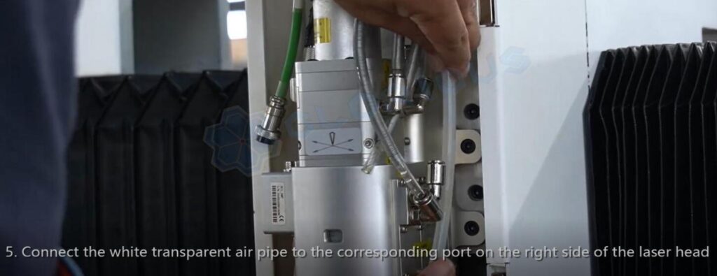
5) Connect the white transparent air pipe to the corresponding port on the right side of the laser head.
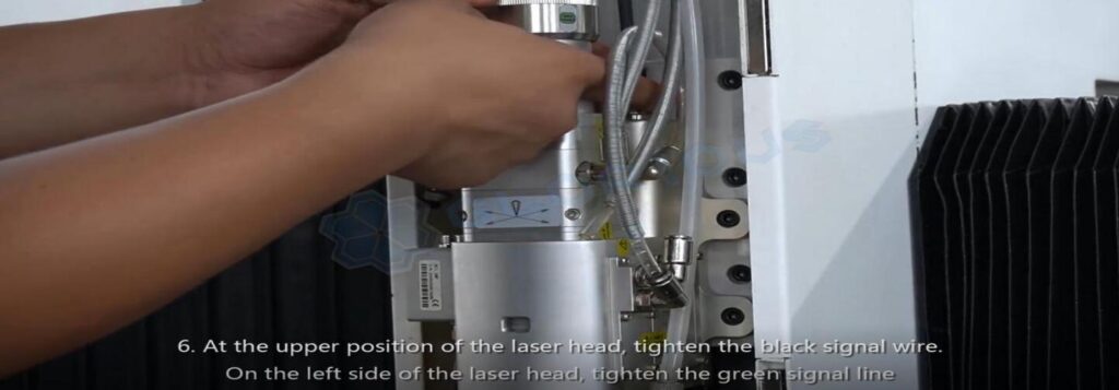
6) At the upper position of the laser head, tighten the black signal wire. Tighten the green signal line on the left side of the laser headline.
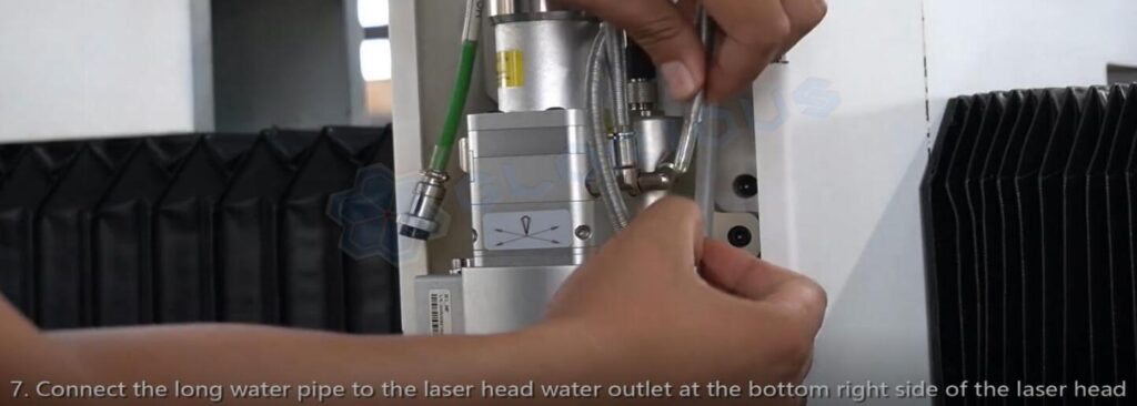
7) Connect the long water pipe to the laser head water outlet at the bottom right side of the laser head.
8) Remove the sealing tape on the water pipe and insert the water pipe into the water inlet on the left side of the laser head.

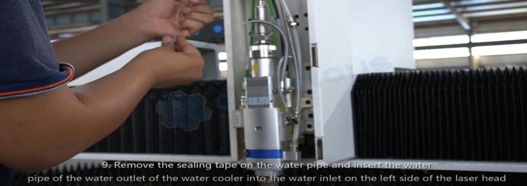
9) Remove the sealing tape on the water pipe and insert the water pipe of the water outlet of the water cooler into the water inlet on the left side of the laser head.
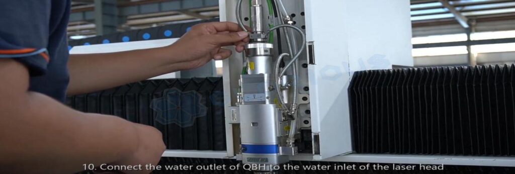
10) Connect the water outlet of QBH to the water inlet of the laser head.
4. Electric cabinet installation
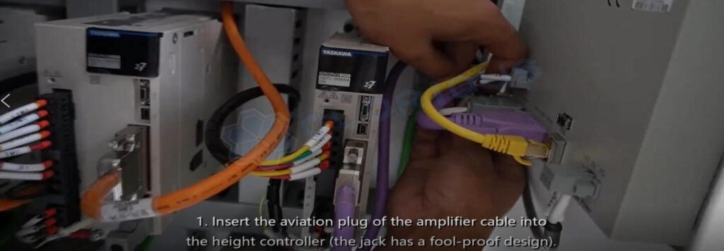
1) Insert the aviation plug of the amplifier cable into the height controller (the jack has a fool-proof design.)
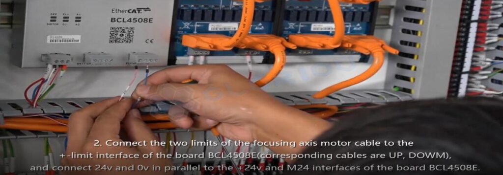
2) Connect the two limits of the focusing axis motor cable to the + – limit interface of the board BCL4508E (corresponding lines are UP, DOWN), and connect 24V and 0V in parallel to the +24v and M24 interfaces of the board BCL4508E.
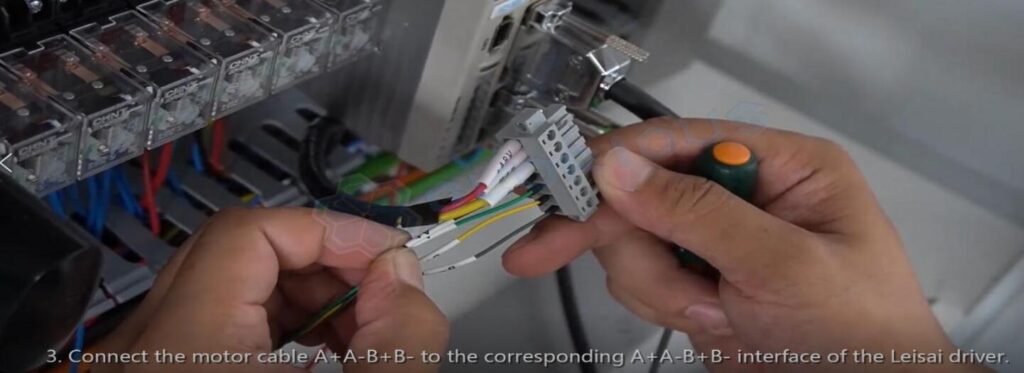
3) Connect the motor cable A+A-B+B- the interface of the Leisai driver.
4) Insert the DB head of the focusing shaft encoder cable into the corresponding DB hole of the driver.

5. Water chiller installation
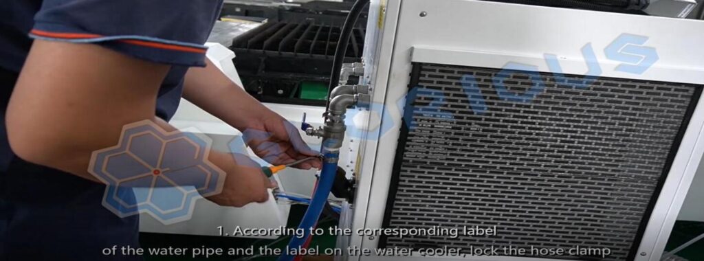
1) According to the corresponding label of the water pipe and the label on the water cooler, lock the hose clamp.
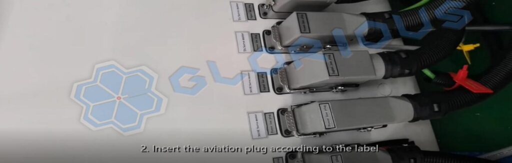
2) Insert the aviation plug according to the label.
6. Laser source installation
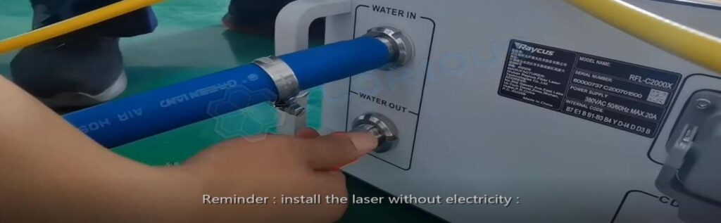
Reminder: Install the laser without electricity
1) Plug the water pipe into the laser Water-in port and the other end of the water pipe into the Water-out port of the water cooler.
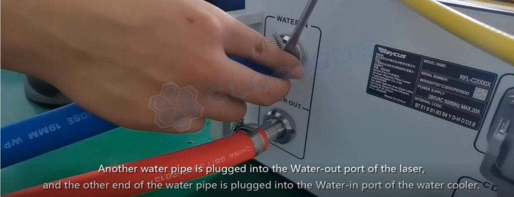
Another water pipe is plugged into the Water-out port of the laser, and the other end is plugged into the Water-in port of the water cooler.
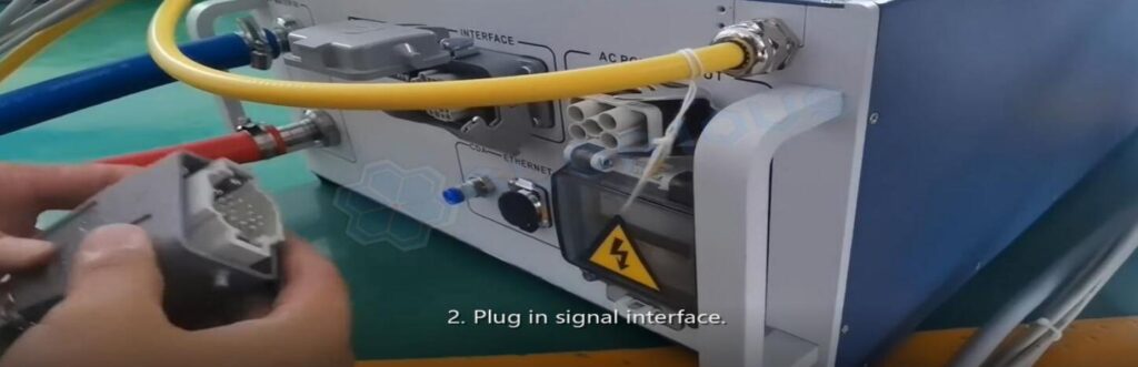
2) Plug-in signal interface.
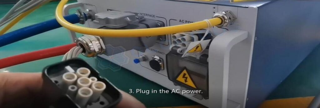
3) Plug in the AC power.
4) Put the laser into the electric control cabinet(2kw and below).
Power on
Check before power on
Note!
① Please make sure your service team is very familiar with all the manuals we sent you, and the following is a guide for reference.
② Please do not power on the equipment at will, and the first metal cutting can only be done after the service team inspection and review.
③ Please read the following instructions carefully after you have mastered it proficiently, then check whether the equipment meets the power-on conditions according to the following instructions
1. First, check the equipment balance, and make sure that each anchor is in close contact with the ground.
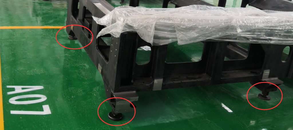
2. Make sure all electricity in the equipment is grounded
3. Add deionized water to the chiller (please prepare antifreeze in cold weather). After adding water, please turn on the chiller first. Check whether there is water leakage in the water pipe at the laser head.
If there is water leakage, immediately turn off the water cooler and check the pipeline connection to prevent water from entering the cutting head through the nitrogen pipeline.
4. After turning on the device’s power, open the operating software, and move the Y and X axis slowly through the handle, full stroke. Otherwise, immediately stop it and contact us.
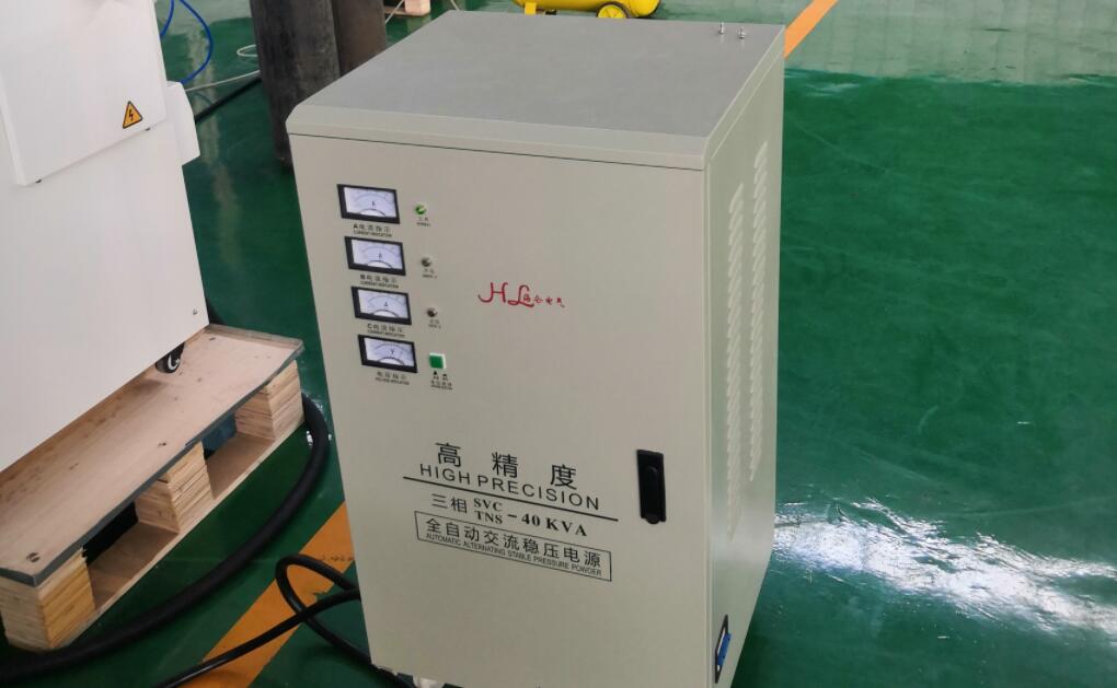
5. The last step is to turn on the laser. The laser must be equipped with a voltage stabilizer to ensure that the output voltage of the stabilizer meets the voltage requirements of the laser. The power of the laser source decides the choice of a voltage regulator.
If there are particular circumstances, please get in touch with us in time.
N2 Pressure needs are in the range of 1.8Mpa~2.3Mpa
O2 Pressure uses 0.5Mpa.
Please inform me which kind of material you would cut and what thickness. That will help the service team to guide you for the following work.
Boot sequence
- Power → computer host → water cooler (temperature to 20-24 degrees)→ laser → software → check gas
- After power-on, find a professional team to debug the machine and other work.
Daily maintenance work and manuals list
Please refer to the details of the cutting machine operating instructions and supporting equipment instructions (because of different configurations, maintenance content is slightly different. Be sure to deal seriously with the cutting software error tips and the first time to solve the error。
The list of manuals
- A circuit diagram (for installation inspection)
- Laser instruction manual
- Instruction manual for cutting head
- Instructions for the use of the cutting machine
- Air Conditioning Manual
- Cutting process debugging specification
- Software instruction video (download the corresponding one)
- Water Chiller Manual
- Warranty Card
Finish Installation ~
Thanks for your trust and support on the GRS laser; please study all the instructions and preparation, then come to the installation step.
This article is only for reference and learning, the main steps by the professional after-sales team to guide.